Real Engineering Review Samples (Anonymized)
Sample DFM Review (Actual Engineering Work)
Excerpts from actual DFM reviews delivered on customer parts — tooling concept, geometry optimization, and risk identification before tooling.
Actual excerpts from customer projects (anonymized for confidentiality).
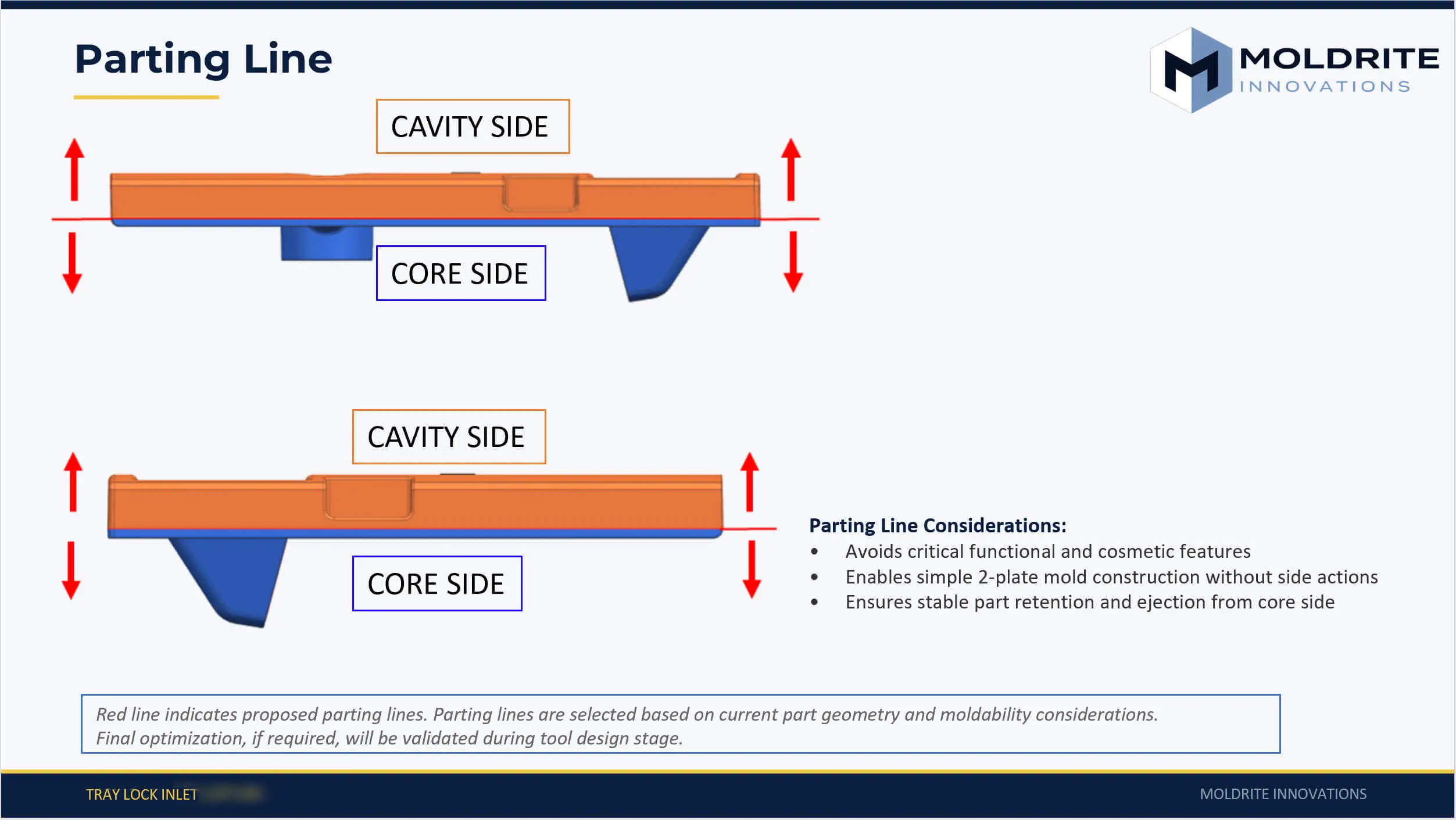
Parting Line Optimization
Parting line defined based on geometry, cosmetic requirements, and tooling feasibility to ensure stable molding and clean ejection.
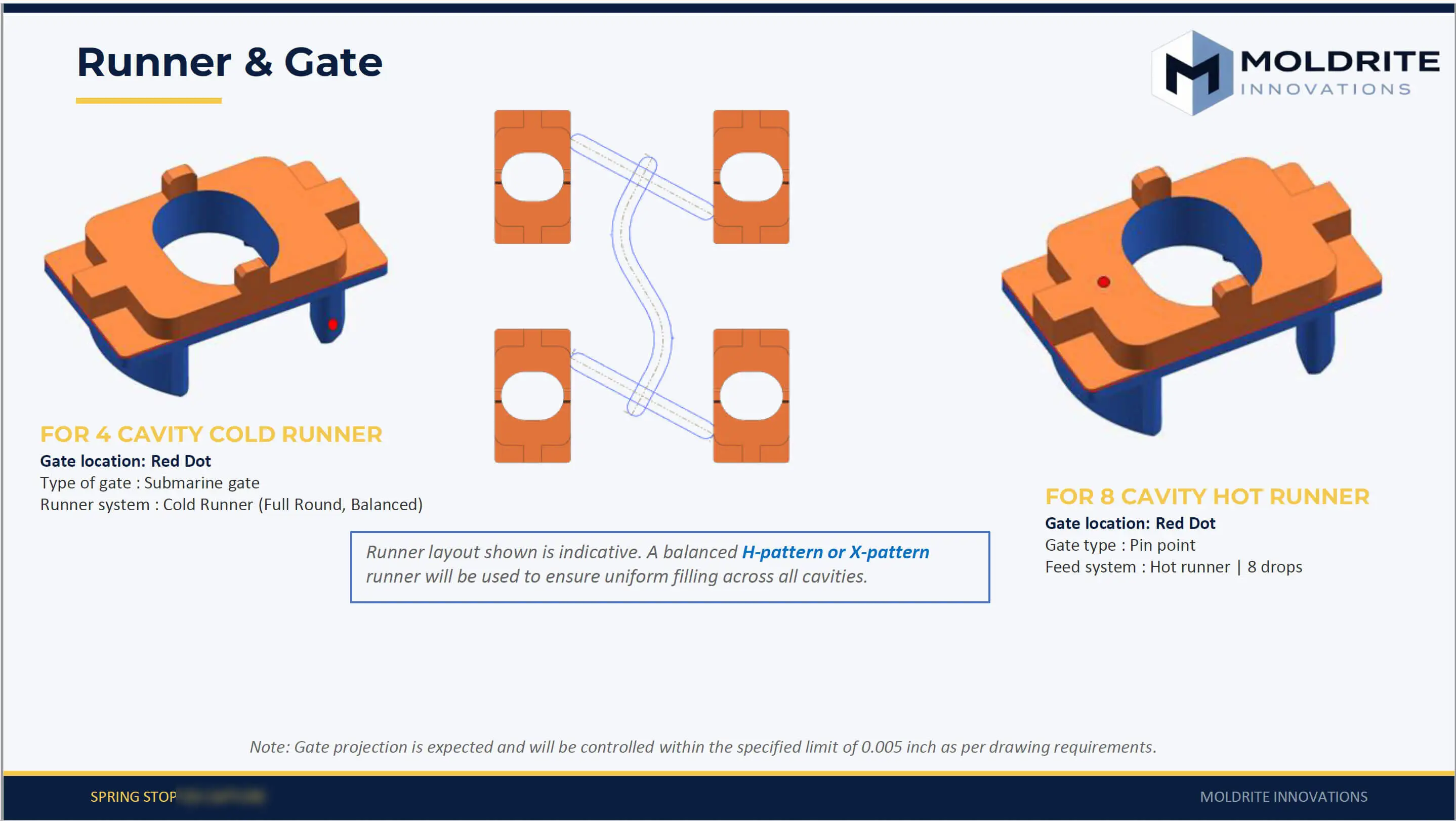
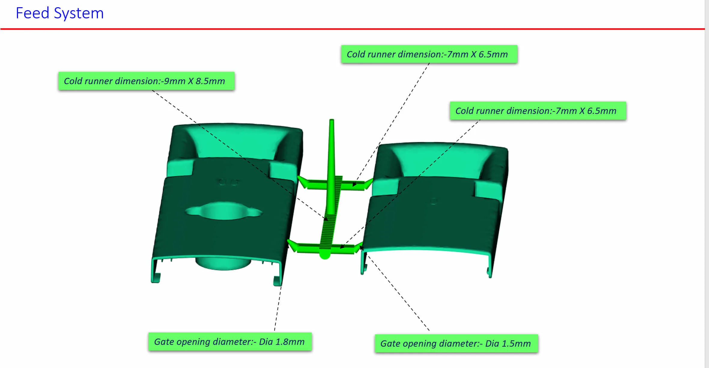
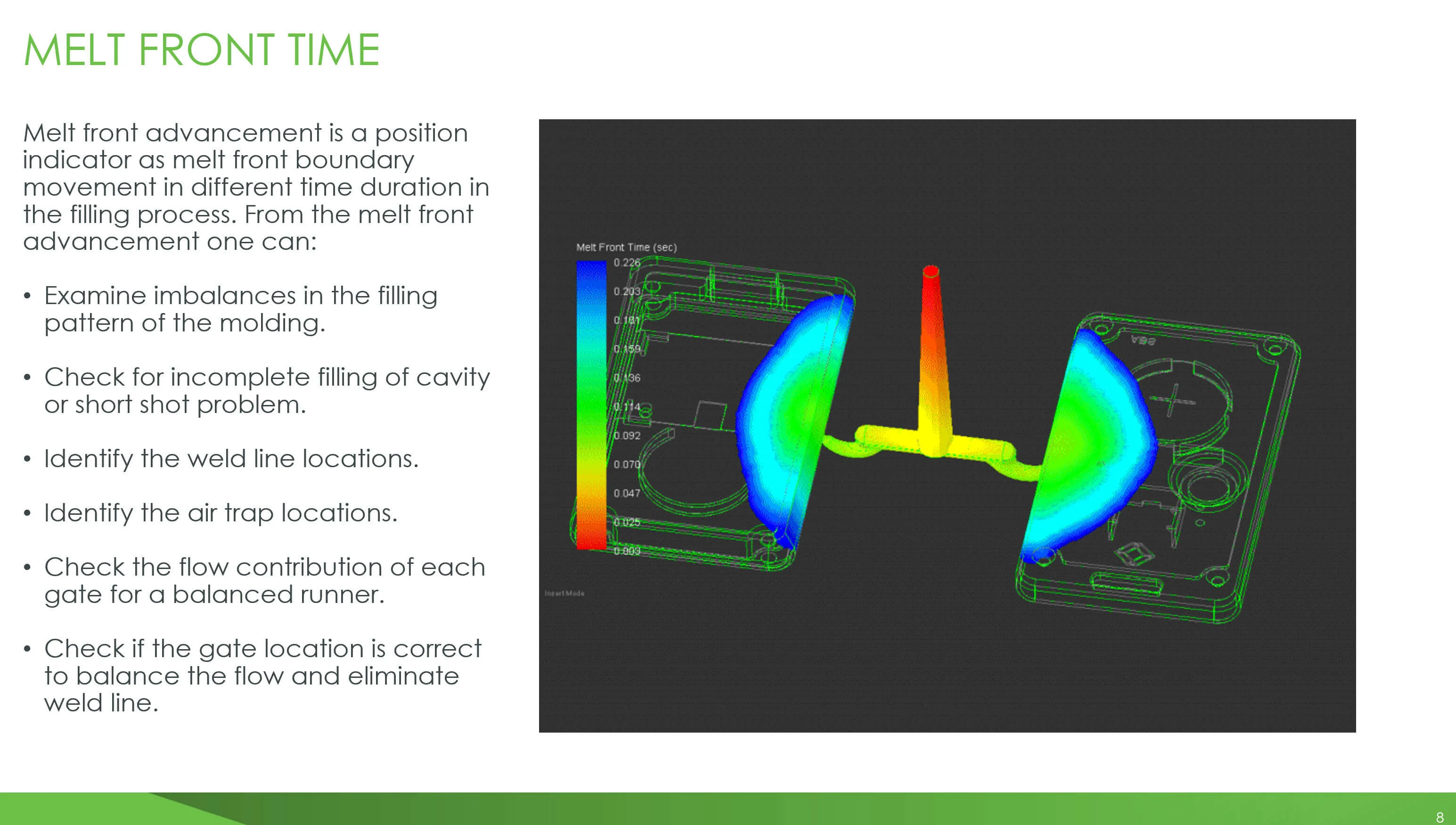
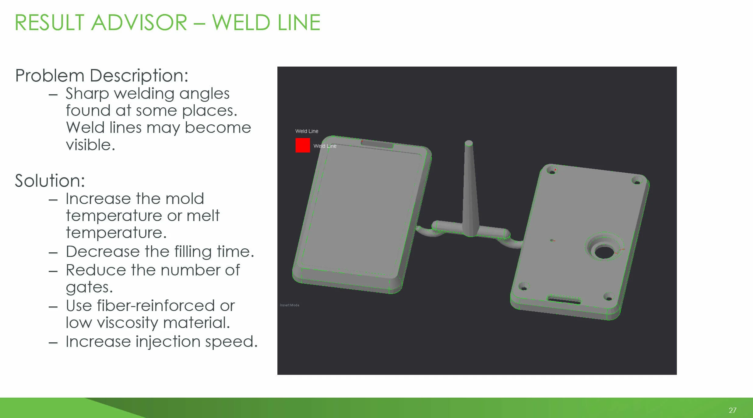
Runner & Gate Design
Runner layout and gate location selected to achieve balanced filling and minimize flow-related defects.
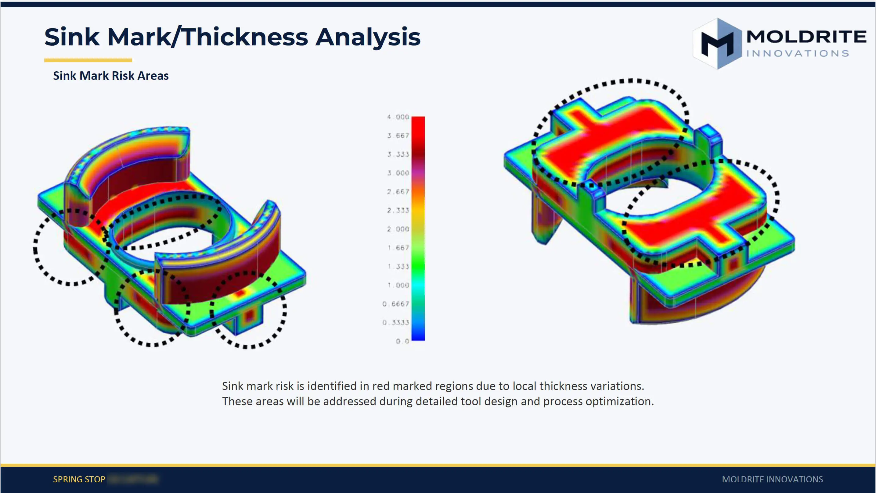
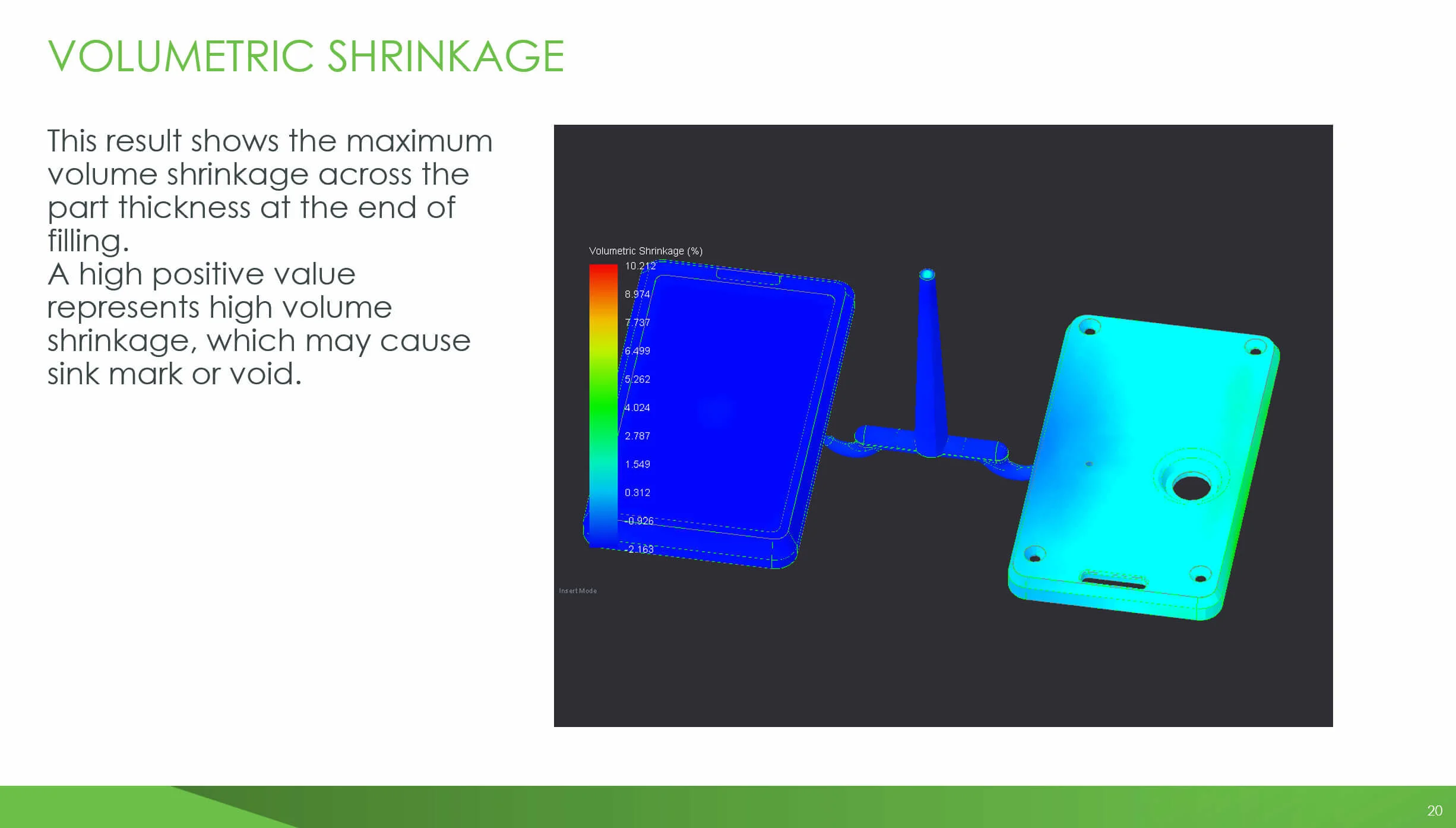
Wall Thickness & Sink Mark Review
Thickness variations analyzed to identify sink risk areas and guide geometry or process optimization.
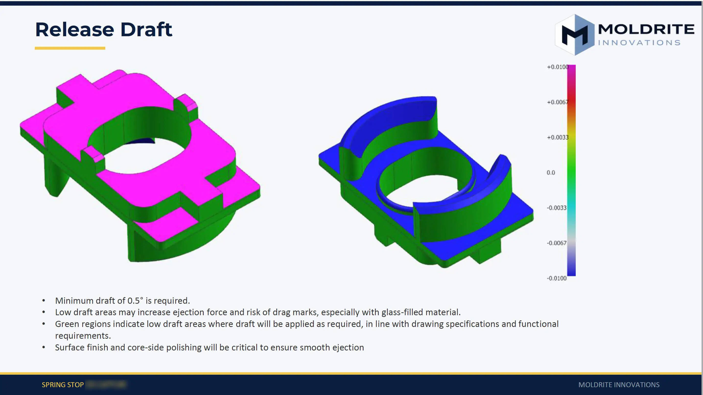
Release Draft Analysis
Draft evaluated across surfaces to ensure clean ejection and prevent drag or surface damage.